This weeks lab assignment is an extension from last weeks Pix4D introduction lab. Ground control points (GCPs) are the focus of this weeks lab assignment. GCPs are used to align the image with the surface of the earth so your results are spatially accurate. The objective in utilizing the GCPs is to produce a true orthorectified image. I will be comparing the accuracy of the results from the same image which I will process twice. The first time I process the images I will utilize GCPs to correct the image and the second processing I will be using GeoSnap to add the geolocation information to the images.
Ground Control Points (GCPs)
GCPs can be:
- Measured in the field using topographic methods such as survey grade equipment.
- Obtained from existing geospatial data
- Obtained from Web Map Service (WMS).
There are three ways in which to add/apply GCPs outlined in the Pix4D manual/help section:
Method A
This method is utilized when the image geolocation and the GCPs have a known coordinate system which can be selected within the Pix4D database. The coordinate systems do not have to match as Pix4D can complete a conversion between the two systems. This method is the most common method to add GCPs to a dataset. The method allows the user to mark the GCPs on the image with minimal manual user input (Fig.1). This method is not user friendly for over night processing.
 |
| (Fig 1.) Outlined workflow for geolocation in a known coordinate system. |
Method B
Method B can be utilized in a few different scenarios:
- The initial images were collected without and geolocation information
- The initial images were collected in an arbitrary coordinate system which is not found in the Pix4D database.
- The GCPs were collected in an arbitrary coordinate system.
This method requires more manual intervention compared to Method A. Instead of having one step to mark the GCPs in the images you have an additional step and a varied order in comparison to Method A. This method is not user friendly for over night processing.
 |
| (Fig. 2) Outlined workflow for geolocation Method B. |
Method C
Method C works for any situation no matter what the coordinate system is of the GCPs or the images. Method C requires the highest amount of user manual input to mark the GCPs on the images. However, this method allows over night processing of the imagery.
 |
| (Fig. 3) Outlined workflow for geolocation Method C. |
GeoSnap
Geosnap is a product produced by Field of View. The GeoSnap Pro is a GPS device which attaches to your sensor (camera) on UAS platforms and produces and log of position and attitude of the camera when the images are captured. Additionally, the GeoSanp Pro can also help manage the triggering of the camera during the flight.
Geosnap is a product produced by Field of View. The GeoSnap Pro is a GPS device which attaches to your sensor (camera) on UAS platforms and produces and log of position and attitude of the camera when the images are captured. Additionally, the GeoSanp Pro can also help manage the triggering of the camera during the flight.
In the following section I will be utilizing and outline the process of Method A to apply the GCP locations to my images.
Methods
During this weeks lab I will be processing 312 images of a local mining facility collected with a Sony ILCE-6000.
During this weeks lab I will be processing 312 images of a local mining facility collected with a Sony ILCE-6000.
Many of the following steps are the same as last weeks lab. If you have questions concerning the basic processing of images please consult my blog post for processing images with Pix4D.
Creating a new project is the first step required to begin processing an image with GCPs in Pix4D. After loading the images into the New Project window you do not have to attach any geolocation information to the images. Make sure you have the correct sensor in loaded the Selected Camera Model Window before proceeding to the next screen.
 |
| (Fig. 4) New Project window with images loaded without geolocation information attached and proper sensor identified. |
Once the project is created and the flight plan is loaded in the viewer the next step is to add the GCPs.
To add the GCPs select Project to open the GCP/Manual Tie Point Manager window. Import your GCP's with the Import GCPs button. Preview you GCP file so you properly select the correct coordinate order. With all of the GCPs loaded in the window check to make sure the Datum is set correct and select ok.
After selecting OK the GCPs will be automatically loaded in to the Map View and displayed as X's (Fig. 6). If the X's do not appear in your flight area then double check the X,Y,Z order of your GCP file to assure you have the correct order. |
| (Fig. 5) GCP/Manual Tie Point Manager with GCPs imported with correct X,Y,Z order and correct Datum. |
 |
| (Fig. 6) GCPs displayed as X's in the Map View window of Pix4D. |
Before processing the image there is once final step required. Under the Local Processing menu you will have to deselect 2. Point Cloud and Mesh and 3. DSM, Orthomosaic and Index before starting the image processing (Fig. 7).
 |
| (Fig. 7) Local Processing menu with only Initial Processing selected. |
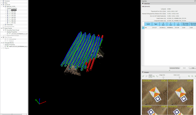
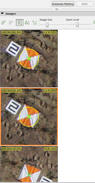
Once the initial processing is complete you will need to reopen the GCP/Manual Tie Point Manager and select rayCloud Editor. The rayClound Editor will open the GCP display properties on the left hand side and adjustment window on the right side of the screen.(Fig. 8).
 |
| (Fig. 8) GCPs display properties (Left) and adjustment window (Right) in Pix4D. |
 |
| (Fig 10) GCP marker flags after applying the first corrections to bring the other marker flags in to view of the remaining images. |
 |
| (Fig. 11) Display Properties menu with the corrected image numbers in brackets after the GCP number. |
 |
| (Fig. 13) Select 2. Point Cloud and Mesh and 3. DSM, Orthomosaic and Index before starting the processing of the images. |
Results
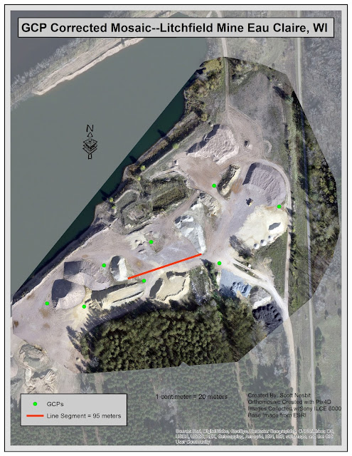
The error for between the two mosaic images is minor when observed in full view. Had the error been more drastic I could have created a map with both mosaics displaying the variance between the two. However, when I brought both of the images into ArcMap you could not tell the difference at the extent need to display the entire mine area. Analyzing where the road connects to the mosaic from the basemap is one of the most noticeable (though very minor) errors with the mosaic (Map 2).
 |
| (Map 1) Display of the orthomosaic created with GCPs data. |
 |
| (Map 2) Display of orthomosaic image created with Geosnap data. |
 |
| (Map 3) 2D display of a 3D image created in ArcScene of the Litchfield Mine. |
Discussion
I first compared the Quality Report of the two projects I ran in Pix4D to see if I could identify the differences. The majority of the values were the same except when I compared the Geolocation Details. The report for the project utilizing GeoSnap displays an RMS error of .36-.44 for the various axis (Fig. 12). The report for the project using GCPs showed the RMS error was between 1.01-1.97 for the various axis (Fig. 13).
 |
| (Fig. 12) Absolute Geolocation Variance chart from Pix4D Quality Report of the mosaic created without GCP points. |
 |
| (Fig. 13) Absolute Geolocation Variance chart from Pix4D Quality Report of the mosaic created with GCP points. |
Does this mean the GeoSnap is more accurate than using GCPs?
Based on the RMS error one would believe the Geosnap is providing more accurate results. To make a comparison I exported the GCP coordinates to a feature class in ESRI Arc Map. Next, I brought in both of the created mosaics for comparison.
 |
| (Fig. 14) GCP location (green triangle) and actual GCP location (orange and white triangle) from Geosnap mosaic. |
 |
| (Fig. 15) GCP location (green triangle) and actual GCP location (orange and white triangle) from GCP mosaic. |
After comparing both the mosaics it was easy to see the mosaic created with the GCPs was more accurate than the mosaic created with Geosnap. I utilized the Georeferance tool in ArcMap to compare the RMS error between the two created mosaics. The results from ArcMap shows the RMS error of the GCP image is lower than the Geosnap image.
 |
| (Fig. 16) RMS Error from the Geosnap mosaic in ArcMap. |
 |
| (Fig. 17) RMS Error from the GCP mosaic in ArcMap. |
Pix4D believes the Geosnap image is more accurate based on the information provided. However, GPS on the camera does not have the accuracy of the GPS unit which collected the GCP locations. The GPS location was collected with a Topcon Hiper and Tesla unit in the same method as I collected point in my topographical survey in my Geospatial Field Methods class. The Topcon has an accuracy of about 3-5 mm depending on the axis. The Geosnap Pro model has an accuracy of approximately 1.5 m.
I feel the Geosnap still has applications in the field. There are many instances where it may not be feasible to layout and collect the information required to produce GCPs coordinates. In very rugged terrain I believe the Geosnap would really shine through and obtain a high enough level of accuracy for the task at hand.
The above discussion displays why the use of GCPs are more accurate and required when performing flights where highly accurate data is necessary. In the following labs we will be exploring additional uses with in Pix4D and utilizing the high level of accuracy which GCPs provide.

No comments:
Post a Comment