The purpose of the lab is to introduce me to the software package Pix4D Pro. Pix4D software has the ability to generate orthomosaic and georeferenced 2D and 3D maps and models from images collected by various methods including UAS platforms.
During this lab I will be creating orthomosaic maps from data captured with two different sensors. The first data I will be processing was collected with a Canon SX260 digital camera. The second set of data I will be processing was collected with a GEMs sensor. For more information on the GEMs sensor see my previous blog post. In the following sections of my blog post I will discuss some of the specifics of Pix4D as answers to questions asked by my professor in the lab assignment. The following section will give you (the reader) a good understanding of the steps required to process data in Pix4D.
Get familiar with the product (questions in italics)
Look at Step 1 in the software manual (before starting a project). What is the overlap needed for Pix4D to process imagery?
Step 1 in the software manual highlights the proper planning to achieve the highest quality results. Collecting all of the data properly in the field will allow for a streamline process and produce quality mosaic images. Step 1 in the manual highlights the necessary minimum requirements your data must meet to create mosaic images.
The recommended overlap for most situations is 75% frontal overlap and a minimum of 60% sidelap (Fig. 1).
 |
| (Fig. 1) Ideal Images Acquisition Plan for General Cases. |
What is the overlap needed if the user is flying over sand/snow, or uniform fields?
Due to snow and sand having large uniform areas it is recommended to have a higher overlap than general landscapes. The recommendations from the manual is a minimum of 85% frontal overlap and a minimum of 70% sidelap.
What is Rapid Check?
Rapid Check is a feature in Pix4D which allows you to check and see if the parameters set in the flight plan was adequate enough to produce a mosaic image. Rapid Check reduces the resolution of the captured images to 1 megapixel (MP) to allow for faster processing. This reduction in resolution leads to lower positional accuracy and can lead to incomplete results. The manual states, "If Rapid Check succeeds then it is safe to assume that the results of Full Processing will be of high quality." Then the manual states if the Rapid Check fails to run that adjustments to the overlap may be needed. Another option would be to fly the mission again to combine both sets of images to try and achieve success of the Rapid Check. The manual also states it is possible to run Full Processing on images which fail the Rapid Check but the results may be of a lower quality and could contain erroneous results.
Can Pix4D process multiple flights? What does the pilot need to maintain if so?
Pix4D can process images collected from multiple flights. There are three parameters you should follow when collecting data with multiple flights.
- Make sure each flight plan captures the images with enough overlap for the situation.
- Make sure there is enough overlap between the two images for proper correlation (Fig. 2)
- Make sure the flights are flown in the same conditions like sun angle, weather, and no new features on the surface.
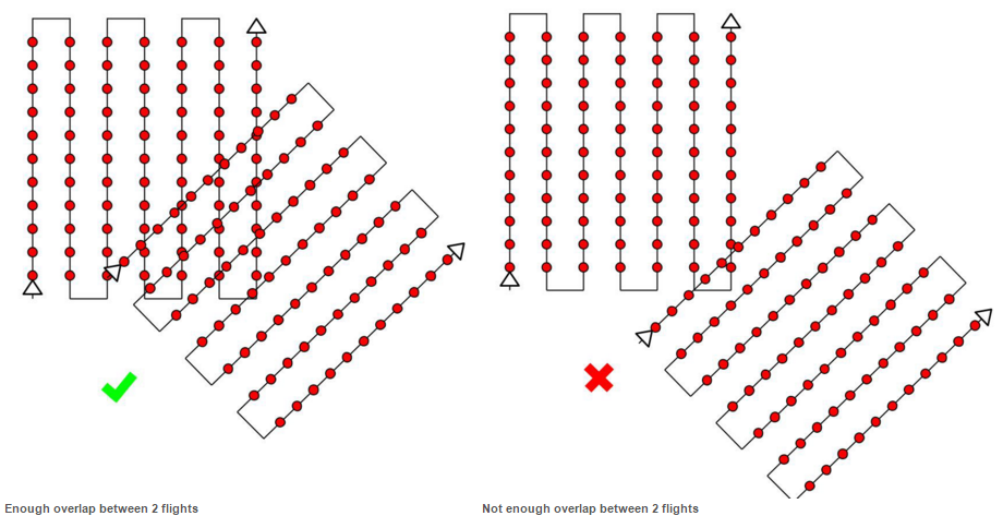 |
| (Fig. 2) Proper and improper overlap between 2 flights display. (Pix4D Manual) |
Can Pix4D process oblique images? What type of data do you need if so?
Yes Pix4D can process oblique images. The example given in the manual is based around constructing a 3 dimensional image of a building. The instructions state the first flight around the building should be at a 45 degree angle (Fig. 3). The following flights should increase in height and decrease the camera angle. The recommendation is to decrease the angle by 5-10 degrees per flight to ensure the images have enough overlap to generate the mosaic image. However, do to variation in spatial resolution you do not want to increase the height more than two times between flights. Processing oblique images results in a very good 3 dimensional image but does not produce a orthomosaic image.
Are GCPs necessary for Pix4D? When are they highly recommended?
Ground Control Points (GCPs) are not necessary when processing images in Pix4D. The use of GCPs improves the global accuracy of the project. GCPs are highly recommend when processing images which do not have geolocation information. While you can still process the images without the GCPs your final mosaic output will not have a scale, orientation, or absolute position information. Without this information you will be unable to complete measurements, perform overlays, or compare previous results.
What is the quality report?
The quality report is like a report card for the images you processed. The report contains almost every bit of information about the image processing results you could think of. The first section is a overview of the project and you will see is a Summary, Quality Check, and a Preview (Fig. 4). The Summary has basic information about the processing such as the name of the project, date and length of time to process, and area dimensions of the processed image. The Quality Check displays specific information about the calibration results between images. The Preview displays and 2 dimensional image of an Orthomosaic and a Digital Surface Model (DSM) image created from the processed images.
Yes Pix4D can process oblique images. The example given in the manual is based around constructing a 3 dimensional image of a building. The instructions state the first flight around the building should be at a 45 degree angle (Fig. 3). The following flights should increase in height and decrease the camera angle. The recommendation is to decrease the angle by 5-10 degrees per flight to ensure the images have enough overlap to generate the mosaic image. However, do to variation in spatial resolution you do not want to increase the height more than two times between flights. Processing oblique images results in a very good 3 dimensional image but does not produce a orthomosaic image.
 |
| (Fig. 3) Proper collection of oblique imagery. (Though they don't follow their own instructions) (Pix4D Manual) |
Are GCPs necessary for Pix4D? When are they highly recommended?
Ground Control Points (GCPs) are not necessary when processing images in Pix4D. The use of GCPs improves the global accuracy of the project. GCPs are highly recommend when processing images which do not have geolocation information. While you can still process the images without the GCPs your final mosaic output will not have a scale, orientation, or absolute position information. Without this information you will be unable to complete measurements, perform overlays, or compare previous results.
What is the quality report?
The quality report is like a report card for the images you processed. The report contains almost every bit of information about the image processing results you could think of. The first section is a overview of the project and you will see is a Summary, Quality Check, and a Preview (Fig. 4). The Summary has basic information about the processing such as the name of the project, date and length of time to process, and area dimensions of the processed image. The Quality Check displays specific information about the calibration results between images. The Preview displays and 2 dimensional image of an Orthomosaic and a Digital Surface Model (DSM) image created from the processed images.
 |
| (Fig. 4) First section of the quality report containing the Summary, Quality Check, and Preview. |
 |
| (Fig. 5) Number of overlapping images reported from the quality report from Pix4D. |
Methods
The following steps are completed after the flight has been flown and downloaded your computer. After opening Pix4D select Project and New Project from the menu bar (top left) to open the New Project window (Fig. 6). From this window you will fill in the name your project and select the location where Pix4D will save the files created during the project process. Under the Project Type select the New Project and then select Next from the bottom right hand menu bar.
 |
| (Fig. 6) New project window in Pix4D. |
 |
| (Fig. 7) Select Images section of creating a new project. |
After the image load you will be brought to the Image Properties window (Fig. 8) The first line in the window will show you the coordinate system which the images are displayed in. Then next line displays how many of the images are Geolocated. The third line shows the camera/sensor which was used to capture the image. Not all sensors are loaded into the Pix4D software. In this case the GEMs sensor was not loaded in and I had to located the sensor specifications and add them to the image properties using the Edit... button. I also had to process images collected by a Canon SX260. When I loaded the images from the SX 260 all of the geolocation information was already attached to the file and loaded automatically.
 |
| (Fig. 8) Image properties window of creating a new project without geolocation information. |
 |
| (Fig. 9) Select geolocation file window. |
After adding the geolocation information your the Latitude, Longitude, and Altitude should no longer contain zeros (Fig. 10). Make sure to check all of your images have been geolocated and filled in. In the last three projects I have ran in Pix4D I have had one image from each which was not properly located. When you find which image does not have any location information attached simply uncheck the Enabled check box to exclude it from the process.
 |
| (Fig. 10) Image properties window with geolocation information. |
 |
| (Fig. 11) Processing options template window. |
With 3D Maps selected I clicked next which brought me to the Select Output Coordinate System window (Fig. 12). I did not change anything in this window and clicked finish to create the project.
 |
| (Fig. 12) Select output coordinate system window. |
Once the finish button has been selected the flight and location of recorded images will be loaded on a aerial imagery basemap with labels in the processing window (Fig. 13). From this window to process the image, you have to select the Start button from the Local Processing menu at the bottom of the screen. The three check boxes which are green in (Fig. 13) will be displayed as red in an unprocessed image. Once the processing has completed for each section they turn from red to green. Processing time depends on the number of pictures you are utilizing to create the mosaic and the processing power of your computer. The minimum system requirements recommended by the manufacturer for medium projects (100-500 images @ 14 megapixels) is 8 GB of RAM and 20GB of HDD Free Space.
 |
| (Fig. 13) Image processing window with loaded project in Pix4D software. |
 |
| (Fig. 14) Post processing display in Pix4D. |
Collecting Measurement from the Results
After creating the orthomosaic, one of the tools with the most practical applications is the measurement tools. The measurement tools allow you to measure straight line distance, area, or volume of a 3 dimensional surface (Fig. 15).
 |
| (Fig. 15) Measure tool bar. Straight line distance (Left), Area (Center), Volume (right). |
To measure an area after selecting the area measure tool, simply draw a polygon around the feature to measure using as many vertices as necessary (Fig. 16). Once you have completed the polygon simply right mouse click to end the drawing which will display the measurement in the upper right hand corner of the screen. The measurement window displays Terrain 3D Length, Projected 2D Length, Enclosed 3D Area, and Projected 2D area. Below the measurement window is a display of the vertical view of the images with vertices (tie points) in them.
 |
| (Fig. 16) Measurement of an island area with in Pix4D. |
To measure a straight line distance after selecting the proper tool, simply select the starting point and when you place the cursor on the point you want to measure to use the right mouse button to create the end point. To display the accuracy of the tool I measure from the start and finish line for the 100m dash at the school track which was in a portion of my image (Fig. 17). The measurement window displayed a Terrain 3d Length of 100.84 m and a Projected 2D Length of 100.78 m. When zoomed all the way in I could see my tie point was past the line which explains the variation in the measurement (Fig. 18).
 |
| (Fig. 17) Measuring the 100 m dash start to finish line using the straight line distance measuring tool in Pix4D. |
 |
| (Fig. 18) Overshoot of the tie point for the line measurement. |
Measuring volume following the same steps as the previous measurements. The only difference is when you right mouse click to create the last point it does not automatically update the volume measurement window. Select Update Measurement button with in the Measurements window. There are various measurement displayed in the window including but not limited to Cut, Fill, and Total Volume.
 |
| (Fig. 19) Volume measurement of a surface in Pix4D. |
The last feature in Pix4D I explored was creating a "fly" through animation video of the mosaic image. Following the help instructions I created way points for the video and the software produced the following video (Fig. 20). To create a "fly" through animation right click on "Objects" when in the rayCloud menu and select New Video Animation Trajectory. From this menu you can create your own trajectory or use the flight path records to create the animation. You have the ability to adjust the speed and duration of the video. Once finished you can export the animation path you have to Render the video before you export it.
 |
| (Fig. 20) Fly through video created in Pix4D. |
Results
 |
| (Fig. 21) GEMs imagery map mosaic of a pond at South Middle School in Eau Claire, Wisconsin. I exported the measurements made in Pix4D as shapefiles and displayed them on the map. |
 |
| (Fig. 22) Canon SX260 map mosaic of a portion of South Middle School in Eau Claire, Wisconsin. |
Discussion
Pix4D is very user friendly program to operate. The methods and tools described above are just basic operations of the program. One of the most useful functions in Pix4D was the ability to export measurements as shapefiles. Displaying measurements on maps is a great way to give a sense of distance to the reader. The help feature and software manual are very useful and easy to understand. When you run into an issue, a simple search leads you to a link with the answers.
The only down side to Pix4D is the amount of processing power and time required to fully process images into a mosaic. The program will crash conventional computers which have low RAM capacities.
The fly through animation was an interesting feature, but like any video files they take up a long of space. I created a longer animation video than the one displayed above but could not embed it in Blogger due to size restrictions.
Overall, I am impressed with the Pix4D software. I look forward to exploring additional tools and uses with in Pix4D throughout the semester.
No comments:
Post a Comment