Introduction
Oblique images collected from aerial platforms serve many purposes in Photogrammetry. When images are collected correctly Pix4D can utilize obliques to create 3 dimensional (3D) models. Additionally, and more importantly Pix4D has the ability to combine 3D model with orthomosaic images allowing the geographic coordinates to be tied to the model. The following blog post will outline the methods and discuss the results from processing and merging an orthomosaic and 3D model in Pix4D.
Methods
For this lab I will be processing a 3D model of a pavilion in a park for stand alone display. Additionally, I will be merging an orthomosaic and separate 3D model from a local farm to produce a single result.
Processing the 3D model from the oblique images follows a similar process with one exception. The analyst should select
3D Models when selecting from the
Processing Options Template instead of selecting 3D Maps (Fig. 1). The remain steps are the same to process the image.
 |
| (Fig. 1) Processing Options Template in Pix4D when creating a New Project. To create a 3D Model the anaylst should select 3D Model from the upper left hand menu. |
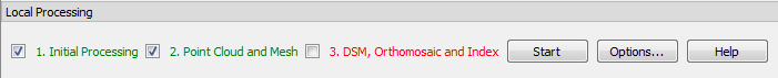
When processing a 3D model it is not necessary to process the DSM, Orthomosaic and Index. The default setting in Pix4D does not check the box to process the DSM, Orthomosaic and Index (Fig. 2).
 |
| (Fig. 2) Local Processing menu in Pix4D with DSM, Orthomosaic and Index unchecked. |
When merging two or more flights together the analyst must first process the imagery from each flight separately. Processing the orthomosaic image is the same process as displayed in my previous
blog post. After processing the 3D model you will be able to create the merged project. You must have both projects in the same
Coordinate System or the projects will not merge together.
After selecting New Project from the Project menu in Pix4D you will change the Project Type to Project Merged from Existing Projects (Fig. 3). In the following window you will add the project files to be merged together (Fig. 4).
 |
| (Fig. 3) New project window with Project Merged from Existing Projects selected. |
 |
| (Fig. 4) Merge Projects window adding the two or more project files together to be merged. |
The final step is to select Finish from the following menu to begin processing the merged project (Fig. 5). The Initial Processing will automatically start when the new project is created. After the Initial Processing has started you can select the Point Cloud and Mesh from the Local Processing menu to process as well.
 |
| (Fig. 5) Finish window when merging projects together in Pix4D. |
Elevation difference between images
One of the issues I ran into was the 3D model seemed to have a different elevation compared to the orthomosaic (Fig. 6 & 7). The way the software is set up you are unable to merge projects which have different datum/projections. However, I certainly had an issue when I merged my two projects together.
 |
| (Fig. 6) Barn roof(s) displayed with two different elevations in Pix4D. |
 |
| (Fig. 7) Barn roof(s) displayed with two different elevation in Pix4D from a futher distance away. |
I created a
Manual Tie Point to reference in the images surrounding the barn area. After creating the tie point I utilized the same method to apply correction to the images as I did in my
GCPs Blog.
 |
| (Fig. 8) Applying image correction through the Tie Point Manager in Pix4D. |
I had to Rematch and Optomize the project and rerun the Point Cloud and Mesh after applying correction to all of the images which contained my tie point.
Results
 |
| (Fig. 9) Resulting 3D Model of a pavilion created in Pix4D |
 |
| (Fig. 10) Resulting 3D Model of a farm created in Pix4D after utilizing tie point correction. |
 |
| (Fig. 11) Resulting 3D Model from a separate flight the same day without tie point correction.. |
 |
| (Fig. 12) Orthomosaic display of the farm for reference of the 3D models. |
Discussion
The first thing I noticed was the 3D model has a tough time with circular and irregular shaped objects such as the silos, trees, and the circular barn roof. The square objects like the sheds are displayed in a much better quality than the round objects.
 |
| (Fig. 13) Displaying the blue silo is very "melted" and the sheds which are square are displayed nicely. |
Another issue the 3D Model has issues with is bright sunlight. When there is intense sunlight the image seems to "melt" and be very distorted (Fig. 14). The fact this building is square did not override the sunlight. I would believe the distortion would have been greater if the building was round.
 |
| (Fig. 14) Display of the sunny side of the image and the melted distortion it caused on a square object. |
Another point to discuss is why the two images of the barn were displayed with two different elevations. The first time I obtained the error I presumed I had made a mistake in one of the base projects. So I started over and ran all of the steps to created new projects to try and cure the issue. However, after trying for the second time I ended up with the same result.
I knew a project of the same location had been successfully merged with good results. After some research into the previous project I determined there were 4 flights flown the day the images were gathered. Two flights were flown collecting nadir imagery for the orthomosaic (Flights 2 & 3) and two flights were flown around the round barn for the 3D model (Flights 1 & 4). For the lab we were given flights 2 & 4. The merged which was successfully projected utilized flights 3 & 4.
I started to investigate the differences in the two nadir flights knowing the 3D model image was the same. Flight 3 had 11 less images and covered a 8.4 acres more than flight 2. I examined the GeoSnap data in addition to the Pix4D quality report to try and identify variances (Fig. 15 & 16). The elevation variance between the flights was very minimal. The
Camera Optimization for flight 2 was poor and did not receive the green check mark as flight 3 did.
 |
| (Fig. 15) Geosnap data (left) and a portion of the Pix4D quality report (right). Flight 2 (top) and flight 3 (bottom). |
The geolocation error was greater in flight 3 compared to flight 2 (Fig. 16). Though as I learned in the previous exercises low RMS error doesn't always equal quality results. I don't know how it really factored in but is still worth noting.
 |
| (Fig. 16) Another portion of the Pix4D quality report. Flight 2 (left) and flight 3 (right). |
None of the report details pointed directly to a factor which is related to the elevation error in the merged image. I don't have the details of the weather the day the flights were made. I believe there were weather factors such as sun and shadows contributing to variation of the images. The weather factors including the snow tied with the lack of GCPs lead to troublesome processing issues.